

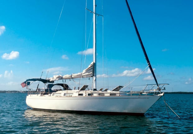
For quite some time, I had contemplated an expansion of the house battery bank aboard our 1987 Sabre 38MKI, Orion. There were several potential issues that had kept the project from becoming a reality. But fortunately, while not trivial, in the end, they were all surmountable, and I was able to install an additional pair of batteries to augment Orion’s overall storage capacity.
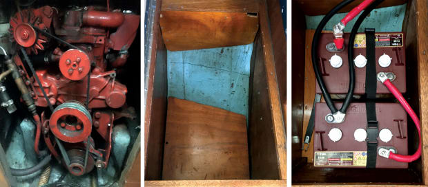
The boat’s original owner had set up a robust system with a standard lead-acid, deep-cycle starting battery and a house bank. The latter was composed of a pair of 6-volt lead acid Trojans wired in series to produce 12 volts while retaining their rated amperage capacity, in this case, 215 amp hours (Ah). There were also a pair of alternators attached to our Westerbeke 38B, the original factory unit, and a 150-amp Balmar, with double pulleys, belted directly to the engine crankshaft. The factory unit is dedicated to the starting battery; the Balmar to the house bank.
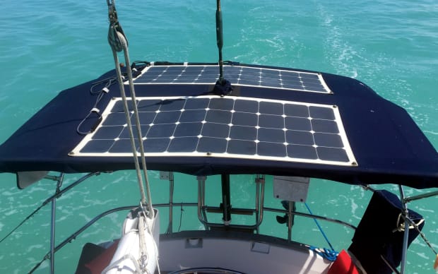
When running the engine, charging is relatively quick and efficient. However, when sailing or at anchor, I only wanted to run the engine as a last resort and had therefore installed a pair of 200-watt flexible solar panels atop the bimini, rated at 92 Ah per day apiece. I’d also installed an MPPT controller for the solar panel-to-battery-bank interface. Finally, to further reduce the electrical load, I replaced every 12-volt incandescent light fixture or bulb, including the navigation lights, with LEDs.
The effective usable Ah capacity for lead-acid batteries is essentially half their nominal rating, since it is generally recommended they should never be routinely discharged below a 50 percent state of charge (SOC). With our previous bank, the effective Ah load should not have exceeded around 107Ah for any given discharge period. In today’s world of refrigeration, autopilots, MFDs, AIS and the like, that’s just not enough for extended cruising and anchoring away from the dock.
The prudent approach to battery-bank sizing is to use a load calculator to determine your boat’s total Ah draw, then build the bank accordingly. In the case of my Sabre, however, doubling the size of the house bank would be the most I could get away with due to space constraints. There simply was not enough space to install more than four batteries in close proximity to one another in addition to the engine and distribution panel. That said, I still thought it would be a good idea to go through the exercise of doing a load calculation, if for no other reason than to identify the boat’s energy hogs.
The toughest task when doing a load calculation is determining the actual Ah draw for the various individual components you have on board. For instance, a VHF radio on standby probably draws less than one amp. However, when transmitting on high power, it may use six amps. Along these same lines, an autopilot struggling to steer in big seas might draw 10 amps, but broad-reaching in fair winds, it may require as little as two. Similarly, 12V refrigeration is generally cycling on and off depending on where the thermostat is set. Run times will also vary with any changes in ambient air temperature. Suffice it to say, one can never arrive at a “true” load calculation. However, reliable specs and reasonable guesses are good enough for most situations. In the case of Orion, the “hogs” proved to be the fridge and the autopilot. We have a Sea Frost 12V compressor-based unit that is pretty energy efficient but still draws four to six amps when on. Similarly, our autopilot is also an efficient one. However, loads can reach six to 10 amps per hour in heavy weather.
Cable Size Matters
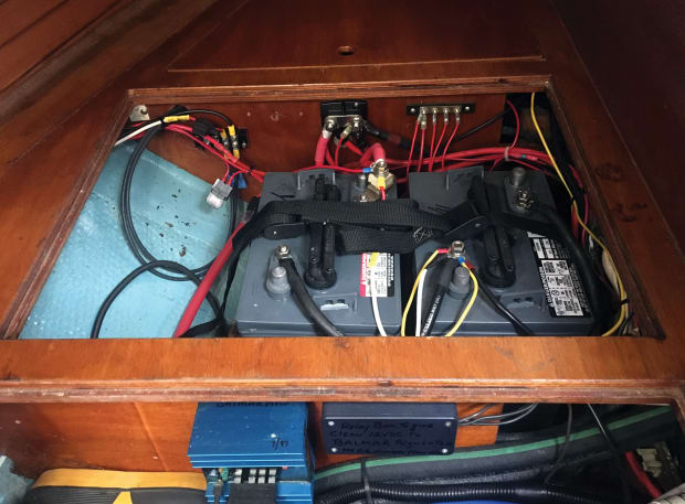
The chosen location for the two additional batteries in my expanded system would be under the navigation bench seat, just forward of where the existing batteries were housed below the quarterberth alongside the engine compartment. The electrical breaker panel is also located in the nav station. This is a fairly typical location on most sailboats. The main battery switch is installed on the companionway bulkhead just above the engine.
Ideally, any additions to an existing battery bank should be as close as possible to the original batteries. Voltage drop is the bane of all 12-volt systems, and the longer the physical distance between batteries, the greater the resistance in the connecting cables. This can result in some serious voltage drop if the cables are not sized properly. Before purchasing new cables, I highly recommend you find and use a battery cable amperage capacity chart, something that is easily obtained online.
Problems can also arise when engaging power-hungry pieces of equipment, like the engine starter motor or a windlass. If the resistance created by an undersized cable during an amperage spike becomes sufficiently extreme, it can melt the cable or even start a fire. Even if there isn’t a fire, the voltage drop could render your equipment inoperable.
Granted, starters and windlasses are typically served by their own dedicated batteries, as opposed to being powered by the house bank. But what if your starting battery inexplicably dies and you need to use the house bank as a backup? For this reason, I prefer all my battery cables be both matched and slightly oversized.
In the case of this particular project, after consulting an amperage capacity chart, I chose 2/0 battery cables. None of my cable runs were in excess of 10ft, and 2/0 cables measuring 10ft or less can handle 300 amps with no more than a 2 percent voltage drop, a safe range for most 12-volt electrical systems.
While on the subject of resistance, unless you own a high-quality cable crimper, I recommend that you buy cables with factory crimped terminals from a reputable dealer. Poorly crimped cable connectors will also create unwanted resistance, again leading to voltage drops and in extreme instances a serious fire hazard.
Installation
The curved inside of the hull also serves as the bottom of the navigation bench compartment aboard Orion, so to start out I fashioned a plywood floor supported by a set of cleats screwed to the compartment’s three wooden sides. That done I attached the new battery boxes to the new floor with stainless steel screws. Holes large enough to accommodate the new battery cables were then drilled into the back corner of the compartment, giving me access to the quarterberth area, which also contains the hot water tank, the Balmar regulator and an assortment of water and electrical lines. The new cables would pass outboard of the water heater and into the compartment where the original two batteries were housed. In doing so they followed the same path as the many wires already passing back and fourth between the distribution panel and the original batteries, engine and peripherals.
After installing the four new batteries (I replaced the batteries in the original bank as well) and securely strapping them down, I set about installing the cables. To obtain the necessary 12 volts, I joined the two six-volt batteries in each location in series. That done, to obtain the amperage I wanted, I joined the two separate banks in parallel. The result is a 12-volt system with an effective usable capacity of 225 Ah, slightly more than double the original bank.
With the cabling installed, the next step was to install a 300-amp fuse block at both positive battery terminals where the positive parallel and positive take-off cables were attached. This was, of course, done to protect against any kinds of potentially dangerous current spikes. As a side note, the positive and negative feeds from the bank should never come from the same end, but from opposite ends to force current to flow through the entire system. This ensures an equal load on each individual battery and ensures the charging source current is evenly distributed as well.
After field-testing the new system by cruising the Bahamas for a couple of months this past winter, I’m happy to report the extra capacity coupled with the solar panels has proven to be more than enough to keep the house bank near 90 percent SOC. This was true even anchored for a full week without once starting the engine. Since the upgrade, our longest nonstop passage has been three days. During that time, there was a much greater demand than usual, with the autopilot, chartplotter, VHF, AIS and running lights all needing power. But the SOC never dropped below 70 percent.
Photos by David Popken
January 2022


